Transformer Bank Wiring Diagram
1/√ 3 × i l of the line current, where i l is the line current. Their percent impedance must be equal.
Transformer Wiring Diagram 480 To 240 Transformer Wiring
None x4x1 h4 h3 h2 h1 x2x3 primary:

Transformer bank wiring diagram. Battery charger transformer wiring diagram. And also discuss how to configure a transformer for use in different applications.inf. Their voltage ratings must be equal.
Connection diagram of open delta transformer. This is a must as otherwise closed delta would mean a short circuit. In which circuit (y or delta) are the phase and line voltages equal?
X1 x2 x3 123456 123456 123456 h1 h2 h3 for additional information, call: (wye) (delta) (delta) wiring diagram 2. H1 x1 x3 x2 x4 h2 123456 h1 x1 x2 h2 123 456 x0 x1 x2 x3 123456123456 123456 h1 h2 h3 wiring diagram 3.
Transformer bank must be sized for 133% of the single phase load (2/3 + 1/3 + 1/3 = 1.33). The first symbol indicates the connection of the primary, and the second symbol is the. Connect the transformer primary according to the wiring diagram on the nameplate.
In general, connecting individual transformers together requires that: The leads or terminals are marked with hs and xs. 100/5 a multi ratio current transformer, with an intermediate tapping on secondary winding.
They learn how to connect the When a single unit or bank of three is used, there are four types of connections. Due to the absence of neutral point it is not suitable for three phase four wire system.
In this video, i'll talk about the basic fundamentals of a transformer. Please find some transformer wiring diagrams below: Read or download the diagram pictures transformer bank for free wiring diagram at burrow.demo.agriya.com
120/240 2, 2 1/2% anfc, 4, 2 /2% bnfc x4 x1 h10 h2 h3 / 12, 2 /2% anfc, 4, 2 1/2% bnfc x4 x1 h10 h2 h3 h1 x2. Overhead electric distribution standards revised:january 1, 2018 revised by:
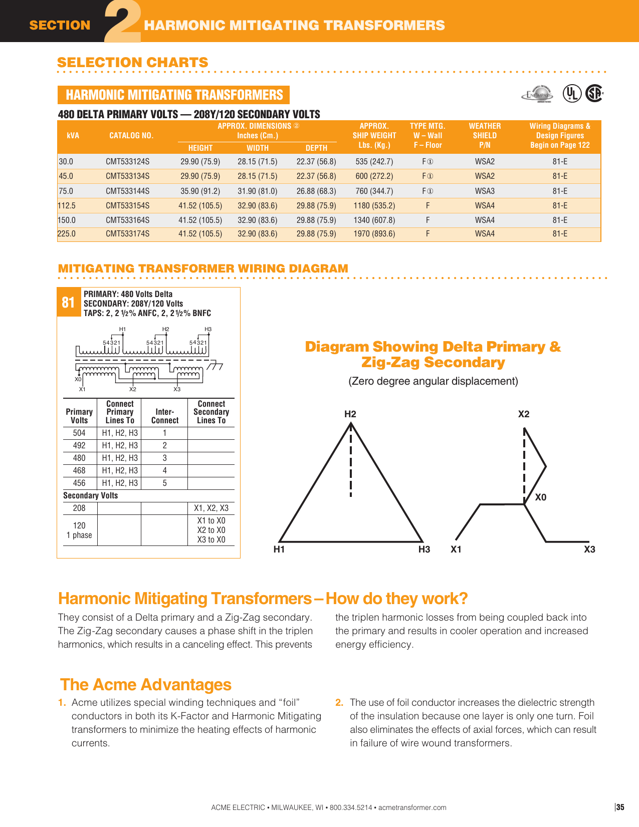
Acme electric u milwaukee, wi u 800.334.5214 u acmetransformer.com 123 generalgeneral electrical connection diagramsacme® transformer™ wiring diagrams primary: The primary or secondary windings may be connected in either star (y) or delta (d) arrangement. The installation of transformers is one of the most common, yet complicated v delta primary to.
A transformer wiring diagram can be found printed on the transformer nameplate or inside the cover to the wiring compartment. None x4x1 h4 h3h2 h1 x2 x3 primary: In a delta connected ( dd ) group of transformers, the line voltage, v l is equal to the supply voltage, v l = v s.but the current in each phase winding is given as:
It is seen from the figure that the sum of the voltages in delta side is zero. The four basic connections are: Ground the enclosure in accordance with nec and local electrical codes.
Wye delta transformer wiring diagram. One disadvantage is feedback on the primary side when a primary phase is lost. Transformer wiring diagram in standard design the terminals of eleq current transformers are marked according to iec.
Please look at attached photos and see if you can give me any insights. The transformer connection diagram is shown in the figure beside. Energize the unit and check the secondary voltage to ensure it is proper for the load.
Each transformer is rated as 10 kva (current rating is 10 a and voltage rating is 1000 v). Can tolerate single line shorts with no interruption. Diagram 3 phase transformer wiring diagrams for bank full version hd quality for bank diagramate prenotasanvito it.
The above figure shows the connection diagram of an open delta system. Transformer wiring diagram for single ratio current transformer. More insulation is required and the voltage appearing between windings and core will be equal to full line voltage in case of earth fault on one phase.
The three transformers in this configuration form a closed loop on the secondary side. 4 bank marine battery charger wiring diagram 12 volt circuit pdf. Draw the connecting wires necessary between the transformer windings, and between the.
Transformer wiring diagrams are printed on the. I would like to re wire it and test it. The four most common connections are.
3 phase to 1 phase wiring diagram in 2021 electrical circuit diagram electrical diagram diagram. 16 220v electric fan wiring diagram wiring diagram wiringg net car audio capacitor capacitor ac capacitor.
Capacitor Panel Control Wiring Diagram at Wiring Diagram
Step Up Transformer 208 to 480 Wiring Diagram Gallery
Wiring Diagram For Transformer
Wiring Diagram For Acme Transformer IZYANNAZIHAH98
Wiring Diagram Of 3 Phase Transformer
Single Phase Transformer Wiring Diagram Complete Wiring
Wiring Diagram For Acme Transformer IZYANNAZIHAH98

SinglePhase Transformers Connected in a Wye Installation

480 Volt Transformer Wiring Diagram Wiring Diagram Networks
Single Phase Transformer Wiring Diagram 7200 Complete
480 Volt Three Phase Transformer Wiring Diagram Wiring
Easy understanding of 3phase transformer connections
Find Out Here Acme Transformer T 1 81051 Wiring Diagram
Transformer Wiring Diagram 480v To 120 240v Complete
32 480 Volt To 120 Volt Transformer Wiring Diagram

Transformer Wiring Diagram 240 Diagram 3 Phase
Transformer Wiring Diagram 240 Diagram 3 Phase
Transformer Wire Diagram H Complete Wiring Schemas

子供向けぬりえ 無料ダウンロード120208 3 Phase Bank